- Stock: In Stock
- Model: CRE8-FUNCTION-JUNCTION
More from this brand
Width = 16hp
Depth = 30mm
Power draw
130mA when running +12V rail
70mA when running -12V
----ADSR / Envelope facts----
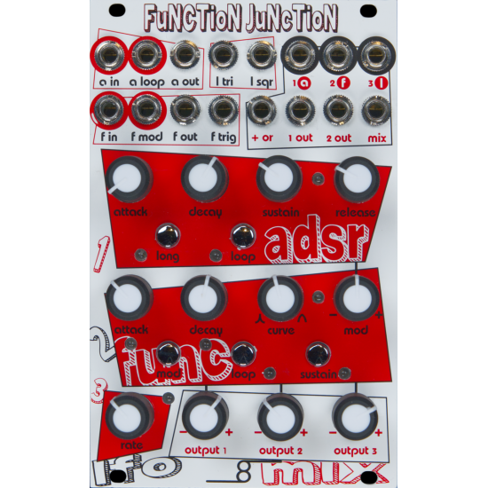
Fully analog Pittsburgh Modular Synthesizers developed 4 stage ADSR circuit with independent Attack, Decay, Sustain and Release controls.
Voltage output range 0V - 10V
“Long” button doubles the length of the envelope attack, decay, and release times
“Loop” button enables/disables envelope cycling. The SUSTAIN KNOB and RELEASE KNOB are used to adjust the time it takes to loop.
“A LOOP JACK” - Enables/disable loop mode. An external gate signal will flip the state of the loop mode. If loop mode is on, the gate will turn loop mode off. If loop mode is off, the external gate will turn loop mode on.
----Function Generator facts----
Function Generator can be used as an envelope generator, a voltage controlled LFO, a slew generator, a gate signal delay, envelope follower, a clock source, voltage controlled clock divider, complex modulation source, and more
Voltage output range +/-5V
ATTACK KNOB - Attack duration control knob.
DECAY KNOB - Decay duration control knob.
CURVE KNOB - Attack and decay response curve. Exponential (full left), Linear (12 o’clock), Logarithmic (full right)
MOD KNOB - Modulation input (F MOD JACK) attenuverter knob.
MOD BUTTON - Assign Modulation input (F MOD JACK) to attack, decay, or both.
LOOP BUTTON - Enable/Disable loop mode.
LOOP BUTTON (2nd FUNCTION) - Press and hold MOD BUTTON then press LOOP BUTTON to assign A LOOP JACK destination to ADSR or function generator.
SUSTAIN BUTTON - Enable/Disable sustain mode.
F IN JACK - Function Generator trigger/gate input gate jack.
F MOD JACK - Function Generator modulation input jack.
F OUT JACK - Function Generator output jack.
F TRIG JACK - Function Generator end of decay trigger output jack. A trigger is output at the end of the decay stage.
----LFO facts----
Triangle and Square LFO outs
Dedicated rate knob
LFO output voltage +/-8V
----Mixer facts----
3 channel attenuverting mixer with OR circuit
Mixer can be split into 3 independent attenuverters, one two-channel mixer, and one attenuverter, or a three-channel mixer
OUTPUT 1 KNOB - Channel 1 input (1A JACK) attenuverter knob.
OUTPUT 2 KNOB - Channel 2 input (2F JACK) attenuverter knob.
OUTPUT 3 KNOB - Channel 3 input (3L JACK) attenuverter knob.
1A JACK - Channel 1 input jack. Normaled to ADSR output.
2F JACK - Channel 2 input jack. Normaled to function generator output.
3L JACK - Channel 3 input jack. Normaled to LFO output.
+OR JACK - Analog logic output jack.
OR circuit outputs the current highest voltage value of any of the voltages output by the mixer
1 OUT JACK - Channel 1 breakout output.
2 OUT JACK - Channel 2 breakout output.
MIX JACK - Mixer output.
-285x169.png)
