

- Stock: In Stock
- Model: DOEPFER-A-101-6
More from this brand
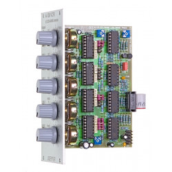
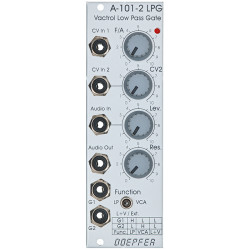
A-101-6 is a new filter module that uses so-called opto FETs to control the filter frequency. Opto FETs are very similar to Vactrols but use light depending field effect transistors (FETs) instead of light depending resistors (LDRs). A opto FET is a combination of a light depending FET and a LED (light emitting diode) both put into a small light-proof case. The advantage compared to vactrols is the much faster response of opto FETs compared to LDRs. This allows much faster attack/decay times and even FM effects. The disadvantage compared to vactrols is that the FET behaves as a normal Ohm resistor only for small levels. With higher levels the FET begins to distort. Apart from this the notes mentioned on the Vactrol Basics page are valid. Module A-101-6 is made of six serial 6dB filter stages. Each stage can work as lowpass, highpass or one of two allpass types. The following schematics show one of the six serial stages in the four possible modes:
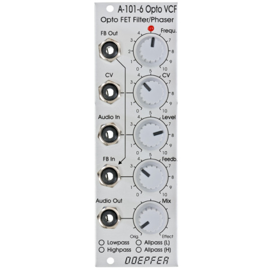
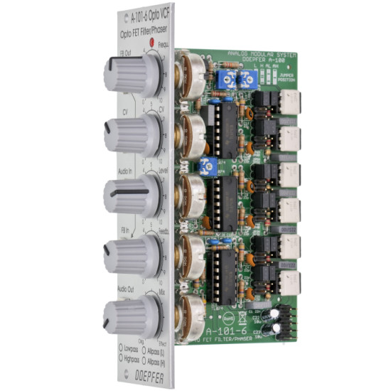
The variable resistors shown in the schematics corresponds to the opto FET. The brightness of the Opto FET LEDs and consequently the filter frequency can be adjusted manually (Frequ. control) and controlled by means of an external control voltage (CV) with attenuator. The LED at the front panel reflects the LED brightness inside the opto FETs. The type of filter is chosen by jumpers on the pc board (factory setting: low pass). The type of filter determined by the jumpers positions can be marked by means of a water-resistant felt pen at the front panel. The following document shows the jumper positions for the four different filter types: A-101_6_Jumper.pdf. The document describes also the adjustment of the trimming potentiometer for the max. resonance/feedback. The resonance is controlled by the Feedback control up to self oscillation. By means of a trimming potentiometer the maximal feedback can be adjusted. High feedback values can be used mainly in the allpass mode to obtain very extreme self oscillation sounds. Even an external feedback signal can be used instead of the internal feedback connection (FB In socket). Whenever the filter type is changed by means of the jumpers the trimming potentiometer for the maximal feedback has to be re-adjusted (see A-101_6_Jumper.pdf last page for details) The Mix control is used to pan between the original signal (CCW position) and the effect signal (CW position). In filter mode (LP/HP) this control is usually set fully CW. In the allpass modes one obtains phasing sounds at center position or "pure" allpass sound in fully CW position. | |
Breite/Width: 8TE / 8HP / 40.3 mm | |
-285x169.png)
