

- Stock: In Stock
- Model: DOEPFER-A-110-4
More from this brand
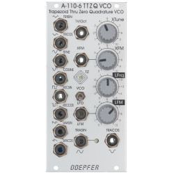
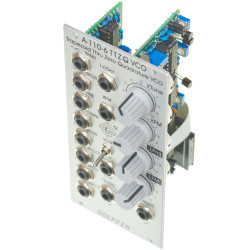
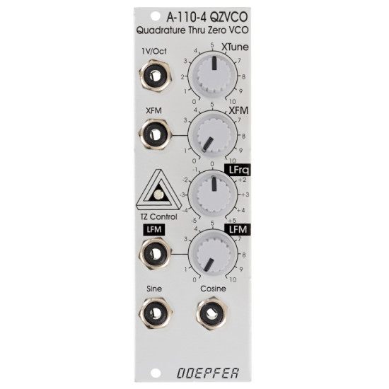
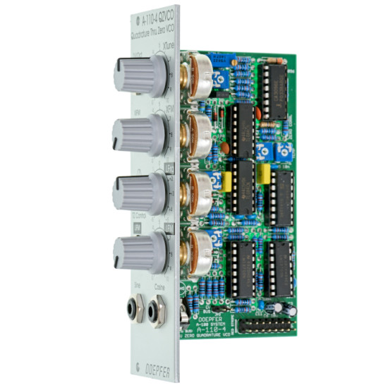
A-110-4 is a so-called Thru Zero Quadrature VCO. The term "quadrature" means in this connection that the oscillator outputs sine and cosine waveforms simultaneously. The term "Thru-Zero" means that even "negative" frequencies are generated. But this a bit a misleading term as negative frequencies do not really exist. "Negative" means in this connection simply that the sine/cosine waves will stop when the linear control voltage reaches 0V and continue with the opposite direction as the linear control voltage becomes negative and vice versa. The module has two control sections: linear and a exponential. The exponential section consists of the XTune control, the 1V/Oct input and the XFM input with the corresponding attenuator XFM. The exponential control voltage is the sum of these three voltages. The linear section consists of the LFrq control and the LFM input with the corresponding attenuator LFM. The linear control voltage is the sum of these two voltages. A dual color LED is used to display the polarity of the linear control voltage (red = positive, yellow = negative). The pitch of the sine/cosine outputs is determined by the control voltages of both sections. The linear section is used to control the pitch in a linear manner. When the LFrq control (LFrq means Linear Frequency Control) is fully CW the module works like a normal Quadrature VCO (e.g. like the A-143-9) and the LED lights red (red = positive). The pitch is then controlled by the exponential section with the manual Tune control XTune and the exponential frequency control inputs 1V/Oct and XFM. 1V/Oct is used to control the pitch by a 1V/Oct CV source (e.g. sequencer or Midi/USB-to-CV interface). XFM is used to apply an exponential frequency modulation with adjustable depth (e.g. from an LFO or another VCO). As the LFrq control is turned counterclockwise starting from the fully CW position the frequency is lowered in a linear manner until the sine/cosine waves (nearly) stops at the center position of LFrq (provided that no LFM signal is present). As the LFrq control is moved from the center towards the CCW position the wave starts again but into reverse direction and the LED turns yellow. When the fully CCW position of LFrq is reached the module works again like a normal Quadrature VCO. But much more exciting is the usage of the LFM input to modify the linear control voltage by an external control voltage (typically another sine VCO like a second A-110-4 - but even normal VCOs can be used). Linear modulation by another oscillator using the thru zero feature generates audio spectra than cannot be obtained from an oscillator without the thru zero function. The reason is that a "normal" VCO will simply stop as the linear control voltage becomes zero or negative. But a thru zero VCO will start again with "negative" frequencies as the the linear control voltage becomes negative. The main advantage of the A-110-4 compared to other Thru Zero VCOs is that the design uses a sine/cosine core. The sine/cosine waves are not derived from other waveforms (e.g. sawtooth or triangle) by means of waveshaping. Rather the sine and cosine waves are the core of the VCO which results in very pure waves with a minimum of distortion and overtones. The output level is about 3Vpp. Audio examples and oscilloscope pictures will follow soon. Important note: Please remove the bus jumper (JP3 "BUS CV") if no CV transmitter is installed on the same bus (e.g. a Midi/USB-to-CV interface A-190-x or a bus access module A-185-x). The A-110-4 applies a small voltage with high impedance (100k) to the CV line of the bus when the bus CV jumper is installed. This may affect other modules that pick-up CV from the bus (e.g. other VCOs). As soon as a CV transmitter is installed on the same bus the high impedance voltage of the A-110-4 is overwritten and no problem occurs ! Additional technical notes: The document A110_4_trimming_potentiometers.pdf explains the functions of the trimming potentiometers. The document is planned only for experienced users ! Please do not change the settings of the trimming potentiometers unless you are sure that you want to change certain settings. Modules which are returned with (mis-)adjusted trimming potentiometers cannot be treated as case of warranty ! The output levels of the module are connected with the waveforms. The two trimming potentiometers P5 and P8 are used to adjust both the level and waveform simultaneously (P5 for the positive share, P8 for the negative share). In the factory they are trimmed for lowest distortion of sine and cosine which results in about 3 Vpp. The settings of the trimming potentiometers P5 and P8 can be changed for higher output levels. But in this case the distortion will increase (i.e. the waveform is no longer a perfect sine/cosine). If the settings are changed one has to pay attention that the levels are the same for the positive and negative share. We think about a small dual amplifier board that can be added to obtain higher levels without the disadvantage of higher distortion. Independent from this an external amplifier can be used to increase the level (e.g. A-183-3). It is also possible to convert the A-110-4 into a Thru Zero Quadrature VCLFO by adding two capacitors to the frequency determining capacitors (C1 and C2). For details please refer to the documentA110_4_trimming_potentiometers.pdf. | |
Breite/Width: 8 TE / 8 HP / 40.3 mm | |
-285x169.png)
