- Stock: In Stock
- Model: RADICAL-FREQUENCIES-DIODE-DREAM-VCF
More from this brand
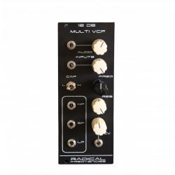
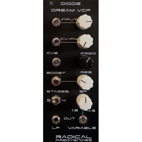
Diode Dream VCF is a 5 Pole diode ladder filter but instead of diodes, the circuit in the filter core section, uses transistors in diode configuration.
The filter has a switch selecting between 5 or 4 STAGES of filtering.
You can access the low pass output via the LP out jack.
There is also a VARIABLE out with a dedicated knob. That knob is a mixer of the different pole outputs that are opposite in phase and in the middle, it gives a band pass [BP] out. When in BP the gain is lower in volume which is completely normal.
VARIABLE mixing knob can be altered from less poles to more poles, more specific, VARIABLE out sends 1 or 2 stages at left side and 4 or 5 stages in the right side. That depends from the position switch of STAGES, so if the switch is in 4 position the VARIABLE out sends 1 (full CCW) and 4 (full CW) stages. If the switch is in 5 position, the VARIABLE out sends 2 (full CCW) and 5 (full CW) stages.
This arrangement also affects the Band Pass slope.
The CV-FM input has a dedicated pot for cv amount that is normaled to the audio input of the filter.
This allows for instant fm tones as the audio input becomes a modulator for the filter frequency.
If there is a jack inserted this connection is broken and you can use this knob as cv amount of an envelope or lfo.
There is one audio INPUT with amount pot and a 2nd CV input jack [CV2].
This CV input can be used as volt per octave input control. When the filter is in full resonance the module can be used as sine wave oscillator with good tuning of 2 octaves.
There is a resonance BOOST switch in order to achieve self oscillation. If the RES knob is fully closed and the BOOST is on, then the filter has still some feedback that would be very useful to emphasise the highs and lessen the low frequencies. When BOOST is off and the RES knob is fully closed and the INPUT level fully open the sound will be a bit oversaturated, so you can try turning down the INPUT level knob at 2-3 o’clock .
The filter has discrete through hole components with low noise transistors that are hand selected one by one with very high hfe values and are also matched in pairs for the buffer differential amplifiers and the input output stages of the ladder. An IC opamp is used for resonance gain compensation.
In the original design when the resonance is turned up the gain of the filter decreases drastically. The filter now has resonance gain compensation and while it still loses some gain when in resonance, the gain difference, is now is acceptable and the sound of the filter is pure and warm without losing the character. The resonance compensation is achieved by increasing the input gain while the resonance opens, so this gives a special character.
Because of the filter design the input signal does not clip instantly but instead it saturates the sound musically and the more you push it the richer the output in harmonics and natural and musical compression.
When the resonance is in self oscillation and the audio input is pushed, the sound gets glassy and squelchy. This filter gets acidic but it maintains the clarity of the high end, yet sounds warm and very rubbery. Detailed bass, creamy mids and crispy smooth highs.
Many different tones are waiting to be discovered by the user dealing in different combinations of the input gain, the resonance, the frequency FREQ knob and the VARIABLE shape of the filter.
- 10hp
- +33mA (+12V)
- -33mA (-12V)
- 58 mm deep
-285x169.png)
