- Stock: In Stock
- Model: RF-LUCKY-VOLTAGES
More from this brand
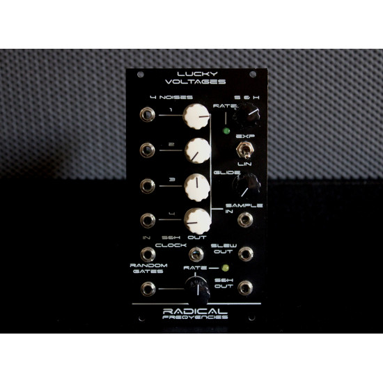
4 Different Noises - Sample & Hold - Sample & Slew - Random Gates - Clock Generator
This is a random module that provides stepped and slewed voltages, allowing the user to dial in the nature, or “flavour” of the random CV and random Gates that are available.
It is also a clock generator and a noise source, providing 4 different kinds of noise, to use in your system
Noise output 1 - Bi-polar favours positive voltages [high output]
Noise output 2 - Bi-polar favours negative voltages [high output]
Noise output 3 - Bi-polar favours negative voltages [low output]
Noise output 4 - Bi-polar favours negative voltages [high output]
NOTE Noise output 4 has a glitchy texture and is dependent on Random Gate Out knob, increasing the frequency of glitch noise, as the Random Gate Out knob, turns CW.
Knob 1 [noise 1 level]
Knob 2 [noise 2 level]
Knob 3 [noise 3 level]
Knob 4 [noise 4 level]
It is important to understand that the S&H Out, outputs random voltages that are a mix of the 4 available noise circuits. Create your own favours of random voltages by programming different settings via the Knobs 1,2,3 and 4 and effectively offsetting the amount of random voltages to the positive or negative range.
Also important is to understand that the Random Gates output is affected by the internal (and external when patched in) clock. Discover settings in your module that effectively, random drop out clock pulses on the Random Gates output, resulting in a “lucky groove” where you can influence the amount of drop outs by programming the 4 noise knobs, and Random Gates, (bottom) Rate knob.
Best to think that this module behaves according to pretty much every combination of knob settings and allows the user to “shape” how randomly it will behave and in what way. The knobs are there to be tweaked and this module begs to be explored!
S&H Clock Out - Internal clock output. Clock time is set by the Rate knob and can reach audio rates.
S&H Clock In - Trigger input for the S&H circuit. You can send a clock or a sequenced trigger to control the rate at which the S&H circuit, samples the internal noise circuits or an external CV that is patched to the Sample In jack.
Glide knob - Sets the lag time that it will take for the random voltages to reach the next value. Linear and Exponential curves are available via the Lin/Exp switch.
Patch tip: Use the Lag Out jack to feed a different set of random voltages that are related to the random voltages, present at the S&H Out, by flicking the switch to the Exp setting and control how much these voltages are related, via the Glide knob.
With the Glide knob at full CCW, there is no slew limiting applied and the voltages present at the Lag Out, are the same as the voltages present at the S&H Out. By applying Glide time the voltages present at the Lag Out, start lagging with relation to the voltages present at the S&H Out.
As a direct result of this process, by increasing the Glide knob, the voltages present at the Lag Out will also cover a smaller voltage range, as they try to catch up with the voltages at the S&H Out, but never quite get there when the Glide knob is turned fully CW.
By flicking the switch to Lin setting, the voltages present at the Lag Out are a copy of the voltages present at the S&H Out.
Glide time applies to both Lag Out and S&H Out.
This provides a nice effect when the switch is at the Exp setting providing two different sets of random voltages, that are related by the Glide time and then by flicking the switch to Lin setting, you “jump” from the two different sets of random voltages to a “unison” set of random voltages that will still follow the lag time, set by Glide knob.
Random Gate Out knob - Controls the rate of the random gates, present at the Random Gate Out jack.
It important to know that, like the S&H Out, the nature of the random gates is dependent on the mix of the 4 available noise circuits. Create your own favours of random gates by programming, different settings via the Knobs 1,2,3 and 4 and the Random Gate Out knob.
The Random Gate Output is not related to the internal clock of the module, nor to an external clock, at the S&H Clock In which allows for some fun feedback patching so make sure to patch the Random Gate Out, into the S&H Clock In for even more random events.
- 30 mA +12V
- 30 mA -12V
- 0 mA 5V
- 75 mm deep
-285x169.png)


