- Stock: In Stock
- Model: ROSSUM-ASSIMILATOR
More from this brand
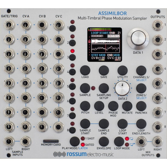
Designed to provide a powerful, flexible sampling engine for modular synthesis, the ASSIMIL8OR Multi-Timbral Phase Modulation Sampler module is the latest incarnation of Dave Rossum’s decades-long pioneering of affordable professional sampling technology.
ASSIMIL8OR provides eight independent channels of sampling with sound quality that can range from extremely hi-fi to low fi, all with extensive real-time CV control.
Key ASSIMIL8OR features will include:
- Eight-channel multi-timbral operation. Each channel will be available from its own independent output as well as appearing in the stereo mix output.
- Superb 24-bit A/D and D/A conversion.
- Mono or stereo sampling. Channels can be configured as eight mono voices, four stereo voices, or any combination. (Well, any combination that adds up to eight).
- The ability to assign up to 8 samples to each channel and select between them in real time via CV.
- DC coupling through the signal path for sampling of control voltages.
- Unique timbral capabilities with the ability to phase modulate samples by external analog signals or by other samples (a first, we believe).
- Variable sample fidelity with independently selectable sample rate and bit depth.
- Real-time CV control of bit depth.
- Real-time CV control of aliasing (from virtually none to lots).
- Extensive sample manipulation and looping capabilities.
- Sample scrubbing under CV control.
- One-shot or gated sample playback with variable attack and release times.
- Gate/trigger inputs and CV inputs for each sample that can be assigned independently for each channel to virtually any sample parameter. Examples include:Pitch
Level
Bit Depth
Phase Modulation
Pan
Scrub
Sample Start
Sample Length
Loop Start
Loop Length
Release Time - A front panel accessible SD card for sample and preset storage.
- And a lot more…
Assimil8or Specifications
SAMPLE MEMORY
2,300 seconds at 48kHz mono, freely allocatable between the 8 channels
SAMPLE RATES
48kHZ, 96kHZ, 192kHZ
A/D & D/A
24 Bits
INTERNAL PROCESSING
32 Bits
LATENCY
100 microseconds at the Mix Outputs
180 microseconds at the Individual Outputs
INPUTS
Sample L/R
2x 3.5mm mono socket
100kΩ Input Impedance
Gate/Trigger 1-8
8x 3.5mm mono socket
100kΩ Input Impedance
1.6V threshold
Control Voltage A 1-8
8x 3.5mm mono socket
100kΩ Input Impedance
96 kHz sample rate
Anti-alias filtered to 20kHz bandwidth
Control Voltage B&C 1-8
16x 3.5mm mono socket
100kΩ Input Impedance
48 kHz sample rate
No anti-alias filtering
OUTPUTS
Mix Outputs L/R
2x 3.5mm mono socket
1kΩ Impedance
Individual Outputs
8x 3.5mm mono socket
1kΩ Impedance
POWER REQUIREMENTS
+/-12V via 16-pin, Doepfer-style connector
CURRENT DRAW
220mA +12V, 30mA -12V
DIMENSIONS
28HP (W); Panel to power connector (with connector plugged in) 25mm (D)
SUPPLIED ACCESSORIES
1x Micro SD card
1x 16-pin, Doepfer-style cable
4x M3 screws
4x M2.5 screws
4x Nylon washers
1x Quickstart GuideDave’s Introduction to Phase Modulation
Phase modulation is a new kind of audio cross-modulation for sampled sounds. It can produce rich and varied timbres and textures, as well as wild distortions and grating noises.
The word “new” is probably not accurate. Modular synthesizers have used frequency modulation (FM) since their inception. Low frequency FM produces nice vibrato effects, and audio rate FM creates interesting timbres. But exponential FM alters the perceived fundamental frequency of an oscillator; linear FM is required to alter the timbre while staying on pitch.
When we use FM, we call the source of the modulation the modulator, and the oscillator being modulated is called the carrier.
In the early 1970’s, John Chowning discovered using digital oscillators that linear FM through the zero point (so the carrier actually reversed its oscillation) produced very diverse and pleasing timbres. Yamaha further developed this technology, but while Yamaha continued to call their implementation “FM”, they actually were using Phase Modulation. Also worthy of note, Don Buchla heard Chowning say that you couldn’t do “through zero” FM with an analog circuit, so Don did just that with his Music Easel’s Complex Oscillator.
Let’s look at some oscilloscope photos to understand the difference. If I frequency modulate a sine wave with another sine wave, the ‘scope shows us the effect on the waveform. (The modulator is on the bottom in blue, the carrier in yellow on the top):

Now let’s use a pulse waveform to modulate a sawtooth wave carrier:

Here you can see that when the pulse is high, the sawtooth gets steep, when it’s low, the sawtooth slope is slight.
Now let’s use “through zero” modulation and turn up the gain of the modulator to show how the sawtooth slope now goes downward (backward) when the FM goes negative:
-285x169.png)
