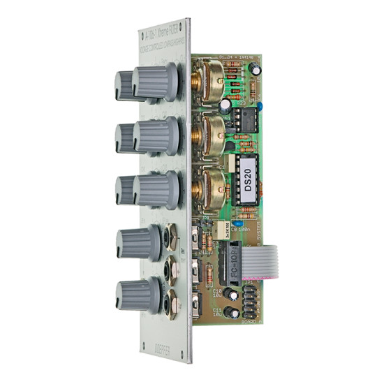


- Model: DOEPFER-A-106-1
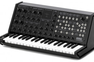
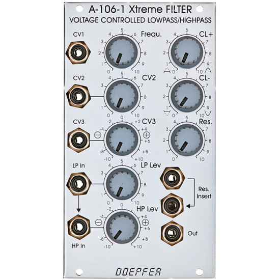
Module A-106-1 has it's origin in our experiments to built a MS20 filter clone. The module is not exactly the same as the MS20 filter but similar. The famous original MS20 included two filters: a 12 dB lowpass and a 6dB high pass filter connected in series both with a very special design (the MS20 highpass if very often described as 12dB high pass, but this is not true). During our researches we found a way to use the same circuit simultaneously as lowpass and highpass for 2 different audio signals (a bit similar to the A-101-1 Steiner Vactrol filter that has even different audio inputs available, but with the special MS20 circuit). For this two separate audio inputs for lowpass (LP) and highpass (HP) with separate level controls are available. The sockets are normalled, i.e. the signal applied to the LP input is available for the HP input too provided that no plug is inserted into the HP input socket. The level control of the HP input is realized as a polarized input. This means that the signal can be added with the same polarity (+ range) or opposite polarity (- range) compared to the LP input. This feature enables notch (+) and bandpass (-) filter functions too. From our point of view this is the most flexible solution that enables e.g. these functions:
| |||||
This design allows even some very special functions: It is e.g. possible to adjust the controls so that the LP signal does not distort but the HP share does (or the other way round) - alternatively with the same or opposite polarity compared to the LP signal. For this the LP level has to be set to a small value so that the signal does not distort. The HP level control has to be set to a higher value (in the + or - range) so that the HP share will distort. On top of this the module is equipped with two frequency CV inputs. One is carried out as a polarizer. This means that effect of the external CV (e.g. envelope from an ADSR A-140 or A-141) to the filter frequency is positive (+ range) or negative (- range). Especially when the filter is moved from LP to HP it might be useful to invert the polarity of the envelope CV. We also have to mention that the frequency response if far from 1V/oct but rather non-linear. To obtain the filter section of the original MS20 two A-106-1 have to be patched in series (one in LP mode, the other in HP mode, both with CL+ and CL- set to zero). It has to be pointed out that the A-106-1 is far away from beeing a "perfect" filter in an academic sense: The control scale is non-linear. With self-oscillation all sorts of waveforms except sine are generated. With high distortion and resonance settings a lot of roaring/rattling/noise or other unpredictible sounds may appear. High distortion/level may "kill" the resonance at certain settings. The filter has a significant control voltage feedthrough and is noisy. The "bandpass" is not a real band pass as a considerable share of all frequencies passes through. The notch filter does attenuate only about 50% at the center frequency - and many more. But the A-106-1 has a lot of character - much more than any other filter of the A-100. It is a very strange and awesome filter - somehow exactly the contrast to the A-108, which is a very smooth, warm and predictable filter. The A-106-1 is definitely not the right choice for "moogish" and "civilized" sounds but for extreme, exceptional and experimental sounds - this is why we call the module "X-Filter". If you want to know more technical details please look at the A-101-1 technical details. In this document the basics of the A-101-1 (Steiner) and A-106-1 filter are described. Included options: For the HP input control can be chosen if the polarizer is active or if a normal attenuator is available. For some applications it might be useful to have the level controls of LP and LP work in the same way (e.g. to obtain the same level for both inputs). With a jumper on the pc board the type of HP level control can be chosen. The CL+ and CL- parameters are prepared to be controlled by external vactrols. Two pin headers are used to establish a connection to the universal vactrol module that is still under development. This will allow voltage control of the CL+ and CL- parameter. Application ideas:
Why the number A-106-1 is chosen for this module? As we think about an MS50 filter clone too .... A detailed description of the module can be found in the user's manual | |||||
Audio Examples The following audio examples show some of the possibilities of the module (so far only sounds with one audio source available, examples with two different audio signals for lowpass and highpass input follow soon). The first three examples are recorded in low pass mode with the following patch: A-110 VCO and A-140 ADSR controlled by an A-155 sequencer, VCO Out = Audio In of A-106-1, ADSR Out = CV In of A-106-1. For all three examples the filter frequency is turned manually from minimum to maximum, then turned back by simultaneous addition of ADSR CV. No other parameter is changed within one example. The A-155 sequence is the same for all three examples: A106_nores_noclip.mp3: Standard low pass mode without clipping and no resonance. The next three short examples are recorded in high pass mode with the following patch: A-110 VCO and A-140 ADSR are controlled by an A-155 sequencer, VCO Out = Audio In of an A-131 VCA controlled by the A-140 envelope, A-131 out = A-106 audio in, frequency of A-106-1 modulated by the triangle output of an A-145 LFO. No parameter is changed manually within these examples: A106_HP_nores_noclip.mp3: Standard high pass mode without clipping and no resonance. The next examples shows the module as a notch filter. The sawtooth output of an A-110 is the audio input of the A-106-1. The frequency is modulated with a triangle LFO (A-145). No resonance. Not very exciting but it shows the varying capabilities of the module: A106_Notch.mp3 A106_LP_fade_in_HP.mp3: This example starts as lowpass and little by little the highpass level is increased. Lowpass level remains unchanged. The next example shows the usage of a spring reverb A-199 with VCA A-130 in the feedback loop. Again the same sequence as in the first examples is used. The two stored random voltages of an A-149-1are used to control the VCA (that controls the reverb feedback) and the filter frequency of the A-106-1. This brings a lot of liveliness in the sequence. The A-149-1 is triggered by the same clock source as the sequencer. No parameter is changed manually during the example! All changes are caused by the A-149-1 only: A106_spring_fb_sou.mp3: Example with spring reverb in feedback loop, amount of feedback controlled by a random voltage | |||||
| Klangbeispiel unseres Kunden Andreas Krebs / sound example by our customer Andreas Krebs: http://blog.andreaskrebs.de/2010/06/18/doepfer-a-106-1-xtreme-filter-example/ | |||||
| Klangbeispiel zum A-106-1 von Kabelton / A-106-1 sound example by Kabelton: http://www.youtube.com/watch?v=vNW6XXvJ74A | |||||
| |||||
-285x169.png)
